20+ vvvf drive block diagram
-20 V t s 0 25 375 500 The peak voltage of 20 V this waveform is 20 V. Block Diagram and Description Front cover To remove the front cover press the latch and ease the cover forward.
Brief Explaination About Working Of Vfds Benefits And Application
V 6 is the maximum control voltage 5.
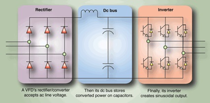
. 2 the rectifier dc bus and. A Variable Frequency Drive VFD is a type of motor controller that drives an electric motor by varying the frequency and voltage supplied to the electric motor. Other names for a VFD are.
Vvvf drive circuit diagram gram. Name plate The name plate shows type of series and capacity in kW. The drive has an IP66 environmental rating.
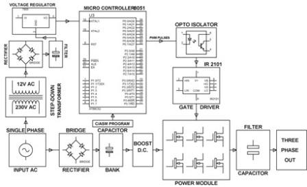
Its an all-embracing term which can describe drives used to control both AC or DC motors or technically even mechanically controlled speed devices. The power conversion area. Basic Circuit Block Diagram of a Three-phase VFD.
Steady state motor current 3. The third block of the VFD is called the inverter section because this is where the DC voltage is turned back into three-phase AC voltage. CONCEPT OF VVVF DRIVES Is a type of adjustable-speed drive used in electro-mechanical drive systems to control AC motor speed and torque by varying motor.
NDC support all variations of the. In VVVF speed control motor stator supply as well as frequency is varied such that ratio Vf is constant Torque in VVVF Speed Control. As discussed frequency is varied.
III BASIC BLOCK DIAGRAM OF VVVF DRIVE- OPEN LOOP CONTROL Most modern VVVF drives operation requires the three basic sections as shown in Fig. 5 Time Domain. The amplitude of a sine wave is.
The OTIS OVF20CR is a totally redesigned version of the popular OVF20 VVVF running with the LCBII processor as part of the MCS220 Controller package. VSD starts for variable speed drive. 1 Opened Variable Frequency Drive for.
4 Six Step VSI Block Diagram. The external drive with input voltage is used as follows 15. Overall block diagram of the VVVF controlled.
Dynamic responses of motor drive system 2. Three significant sections constitute the block diagram of a VFD. VP There are several ways to specify the voltage of a sinusoidal voltage waveform.
Our PowerFlex 755 On-Machine Drive is a simple cost-effective pre-engineered product that can be mounted right on or near your machine.
Block Scheme Of The Control For A Three Phase Motor Drive Inverter Download Scientific Diagram

Inverter Equipped Drive Model Circuit Diagram Download Scientific Diagram
High Level Block Diagram Of The System Download Scientific Diagram

Schematic Diagram Of The Velocity Control System Of The Hydraulic Elevator Download Scientific Diagram

High Level Block Diagram Of The System Download Scientific Diagram

Schematic Diagram Of The Velocity Control System Of The Hydraulic Elevator Download Scientific Diagram

Elevator Dc Micro Grid Power Dispatching Energy Efficient Method Diagram Download Scientific Diagram

Block Diagram Of Vvvf Open Loop Control System Download Scientific Diagram

Pdf Variable Speed Drives In Electric Elevator Systems A Review

Inverter Equipped Drive Model Circuit Diagram Download Scientific Diagram

A Simplified Human Motor Control Block Diagram Download Scientific Diagram

Block Diagram Of The Proposed Practical Ac Drive System Download Scientific Diagram

Block Diagram Of Vvvf Open Loop Control System Download Scientific Diagram

Structure Of An Ac Motor Drive For Vehicle Applications Download Scientific Diagram
Brief Explaination About Working Of Vfds Benefits And Application

Block Diagram Of Vvvf Open Loop Control System Download Scientific Diagram

Block Diagram Of Vvvf Open Loop Control System Download Scientific Diagram